


February 28, 2017
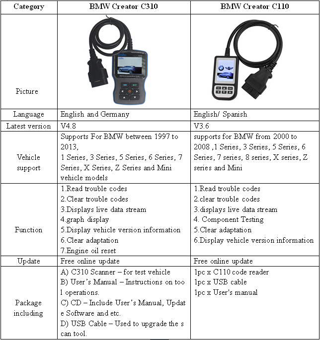
AUTOPHIX ES910 is a handy professional OBD diagnostic scanner for BMW/Mini/Rolls-Roycecovering Engine ABS Airbag Gearbox full-system. ES910 scan tool comes withspecial function: CBS reset, Engine clear adaptions, battery management, EPB electronic parking brake,SRS system,learning valve limit position.
Multi-language:English, French, Spanish, Germany (More language will be added)
AUTOPHIX ES910 BMW Scanner Function:
1. Read/Clear trouble codes
2. Version Information
3. Displays live data stream and graph display and vehicle version information
4. Clear adaptation
5. ABS, Airbag, SAS,EPB System Reset
6.Read data stream

AUTOPHIX ES910 Full-System BMW Scan Tool Special Functions:
1. CBS Reset/CBS Correct
CBS Reset 1 : Engine oil, Spark plugs, Front brakes, Rear brakes, Coolant, Diesel particle filter, Brake fluid, Microfilter, Vehicle inspection, Exhaust emission inspection, Vehicle Check.
CBS Reset 2 : Oil service, Inspection, Time interval, Correct follow-on service, Dislay service interval status.
CBS Correction: Engine oil, Spark plugs, Front brakes, Rear brakes, Coolant, Diesel particle filter, Brake fluid, Microfilter, Vehicle inspection, Exhaust emission inspection, Vehicle Check.
2. Clear adaptations
3. Battery management
4. EPB Electronic Parking brake
5. Steering-angel sensor
6. Learning Valvetronic limit positions


Autophix ES910 Diagnostic Scan Tool User Manual
AUTOPHIX ES910 OBD2 Scanner SupportsforBMW & MINI between 1998 to 2013:
For BMWbetween 1998 to 2013:
1 Series: 1’_E81/E81/E87/E88, F20
3 Series: 3’/Z3_E36, 3’_E46, 3’_E90/E91/E92/E93, F30
5 Series: 5’_E39, 5’_E60/E61, 5’_GT(F07), 5’_F10/F11/F18
6 Series: 6’_E63/E64, 6’_F12/F13
7 Series: 7’_E38, 7’_E65/E66, 7’_F01/F02/F03/F04
X Series: X1_84, X3_F25, X3_E83, X5_E53, X5_70, X6_E71
Z Series: 3’/Z3_E36, Z4_E85/E86, Z4_E89
For Mini
Include : Drive , Chassis and Body all system
R50: "Mk I†Mini One & Cooper (2001–2006)
R52: "Mk I†Mini Convertible (2004–200![]()
R53: "Mk I†Mini Cooper S (2001–2006)
R55: "Mk II†Mini Clubman (2007–present)
R56: "Mk II†Mini Hatch/Hardtop range (2006–2013)
R57: "Mk II†Mini Convertible (2009–present)
R58: Coupé (2012–present)
R59: Roadster (2012–present)
R60/R61: Countryman (2010–present)
F54/F55/F56
For Rolls Royce:
All of RR Chassis systems
RR1,RR2,RR3,RR4,RR5
BMW ES910 support systems:
CAS, DDE, DME, EGS, MRS/ACSM, ABS/DSC, IHKA, KOM/INSTR, EMF etc.
AUTOPHIX ES910 Specifications:
Display: Backlit, Colorful, 320×240 pixel
Operating Temperature:0 to 60°C (32 to 140 F°)
Storage Temperature: 0 °C to 80°C (32 to 176 F°)
External Power: 8.0 to 18.0 V power provided via vehicle battery
Dimensions:
Length Width Height
170mm 96.5 mm 29 mm
0.58kg

http://blog.obdii365.com/2017/02/27/autophix-es910-bmw-scanner-for-engine-abs-srs-gearbox/
Posted by: jean at
02:42 AM
| No Comments
| Add Comment
Post contains 379 words, total size 9 kb.
February 27, 2017
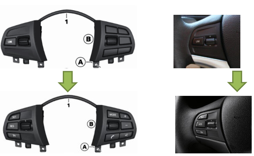
What does this DIY do?
Replace and code multifunction steering-wheel switch from LIM function to dynamic cruise control capability on BMW F20 or F30. This will allow the car to have dynamic cruise control capability. The set speed can be selected from 30 km/h to 180 km/h: in convenient steps of 10 or fine steps of 1. The set speed is displayed on the instrument panel via speedo dial and briefly on information display.
Dynamic Cruise Control Dynamic cruise control is an electronic cruise control system with an extra braking function. This also includes the Curve Speed Limiter that reduces the speed in curves for comfortable lateral acceleration. At the end of the curve the car accelerates and resumes the original speed. The driver can change this in increments of 1 or 10 km/h. Acceleration and deceleration in two dynamic settings can be controlled by manipulating the lever on the steering.

Brief component description:
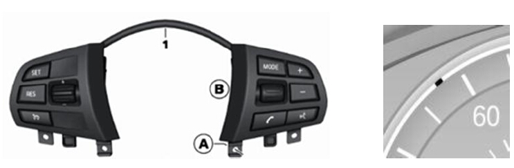
Multifunction steering-wheel switch
The multifunction steering wheel contains a horn switch and airbag plus, depending on the model, buttons for controlling the radio, telephone and cruise control. The buttons are split between 2 switch blocks; left and right.
Functional description
The left multifunction steering wheel switch block is directly connected to the right one via a plug connection. This means that all the button signals in the left multifunction steering wheel switch block are detected and digitised in the electronics of the right switch block.
The right multifunction steering wheel switch block sends the signals via the local interconnect network bus to the steering column switch cluster. The steering column switch cluster is the data interface between the local interconnect network bus and FlexRay. All button signals are sent as FlexRay messages.
The right multifunction steering wheel switch block is directly connected to the left one via a ribbon cable.


This DIY will guide you on how to change/code the multifunction steering-wheel switch with cruise control function. The bimmer can be either F20/F30 series with automatic air condition.
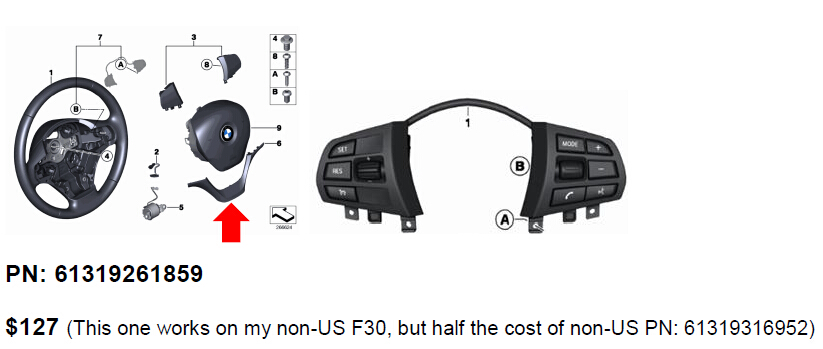
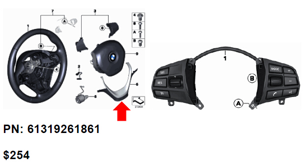
Part required:
BMW OEM Multi steering-wheel switch
Note the different in the trim piece highlighted by red arrow.
Leather steering wheel
Sport leather steering wheel
Tools required:
1. Flat head screw driver
2. Torx screwdriver T10, T20

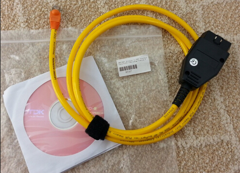
3. Computer with esys installed
4.BMW ENET cable(Ethernet to OBDII) usb interface
5. ESD strap

6. Wrench 10 mm
Installation Instruction for Multifunction Steering Wheel Swtich:
There are two ways to remove air bag. I recommend to remove air bag using the below method as it is easier plus it will not leave any mark on the steering wheel. The BMW method is in the appendix, if you desire to do that way. The toughest part of this DIY is getting the air bag out.
1. Disconnect negative battery terminal.
a. This will add safety from unintentional air bag deployment during removal.
Important!
Do not under any circumstances use force to pull off negative terminal.
Pull off battery earth lead with IBS in an upwards direction, place to one side and secure.

2. Removing upper section of steering column shroud


4. Turn steering 90 degrees to as illustrated below

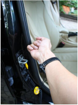
5. Look back to the steering wheel from behind underneath steering column for the air bag hook as the picture below and use flat head screw driver to pry the hook and pull the air bag up on same side. Once the air bag is release continuing on the other side above the steering column to get the air bag release from both hooks. After remove airbag turns steering back to normal position.

6. Disconnect airbag and multifunction steering switch electrical connectors from the steering wheel.

7. Remove the air bag and put it in an open space with BMW logo facing up.

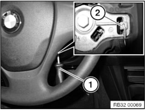
8. Use Torx screw driver to loosen two screws to release the multifunction steering switch and trim from steering wheels.
9. Use Torx screw driver to release multifunction steering switch from the trim pieces (4 screws) and replace with new multifunction steering switch. (Need to transfer one electrical connector from the old switch to the new multifunction switch.)

10. Reinstall trim piece to steering wheel and route the wire back to steering wheel.

11. Reconnect the connectors for multifunction switch and air bag and install air bag back by pushing it in until you hear a snap. Check to make sure that air bag is secured firmly.
12. Assemble back the steering column shroud and aerial.
13. Reinstall the steering gap cover.

14. Move steering column to the normal driving position.
15. Reconnect negative terminal.
16. Press start and check the followings:
a. Illumination lights on multifunction steering switch
b. Check the audio control
c. Press horn to check
d. Check for any fault from the instrument panel. Should be none!
17. Start coding
Coding:
Before you do this coding you must already know how to do coding, please search Google
on how to do or where to get theBMW ENET cableand E-sys software. I only let you know the step and ECU to do
FA coding
FA Coding:
1. Launch esys and connect to your car
2. Select expert mode
3. Read and activate FA (add option 544)
4. Read SVT
5. Select and code the following ECU
a. FEM
b. ICM
c. KOMBI

6. If you want "LIM†function, you will need to do FDL coding per the table below. This will
allow "SET†button to act like "LIM†button so that you get both LIM and Cruise controlfunctions.

Testing:
1. Start the car and drive away
2. Once on an open road and the speed is greater than 30 km/h press button to turn oncruise control. The cruise indicator should be lit in the instrument cluster.
3. Press "Set†to set cruising speed then let go gas pedal, if the car can maintain the speed youall done.

4. Fine a bridge/slope and check whether the brake is applied when going down to maintainspeed.
5. You all set! Consult owner manual for full detail of cruise operating procedure andprecaution.
Appendix:
Removing and installing/replacing airbag unit

Observe the following instructions to avoid any risk of injury by the airbag unit.
-Comply with safety regulations for handling components with gas generators.
-Do not exert any force on the airbag unit.
-Use only specified tools for releasing the airbag unit.
Note: Incorrect handling may result in triggering of the airbag unit and thereby cause serious injury
Necessary preliminary tasks:
ï‚· Disconnect battery earth lead
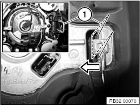
Insert Torx screwdriver T20 (1) vertically into the concealed opening until limit position (2) can be felt.
Pull Torx screwdriver (1) approx. 2-3 mm out of opening. Press screwdriver handle towards middle of steering wheel and simultaneously slide into opening to position Torx screwdriver behind retaining spring bracket (refer to graphic below)
Press retaining spring bracket (1) of airbag unit inwards and simultaneously pull airbag unit upwards until it unlocks.
Repeat procedure on other side.
Installation note:
Snap airbag unit with uniform pressing force plane-parallel in direction of steering column shaft into steering wheel.
Warning!
Danger of injury!
The airbag unit may only be set down with the airbag itself facing up.
Tilt airbag unit forwards.
Disconnect plug connections (1) and remove airbag unit.
Installation note:
Make sure electrical leads are correctly positioned.

Posted by: jean at
01:57 AM
| No Comments
| Add Comment
Post contains 1434 words, total size 23 kb.
February 25, 2017
SomeBMW INPA K+DCAN Cableneeds a modification to work on newer or older BMW cars. older vehicles requires the pin 7 and 8 to be bridged to work..3/2007 and later requires pin 7 and 8 to be separate.
Tools needed..
1. Small philip screwdriver
2. micro on/off switch (can be two prongs or three)
3. Soldering gun
4. Some type of glue gun or glue adhesive
5. and something to make a hole in de DCAN cover for the switch
Locate pin 8 which will have a number on the side of the board. One side will have the digit 1 and the other digit 8.
Once you locate pin 8, that’s the pin we will be using as well as the next one over. Connect each pin 7 and 8 with a separate wire and then use the soldering gun and connect each wire to the micro on/off switch… If you bought a 2 prong on/off switch connect it to each side, but if you bought a switch with three prongs, connect the middle and one of the ends, doesn’t matter which one. At the end there will be one prong end not used…Neatly place the wires snug so that the D-can cover can be closed without anything preventing it to make a closed seal and your done. Screw in the 4 philip head screws in their respected holes. Note which position is on and which is off by some type of label on the outside of the cover…Simple! Note on my first pic, I have a switch with 3 prongs, but I snipped off the 3rd one just to make it easier to solder…

I have tested it and it worked. My K+DCAN Cable work on all E-Series cars, doesn’t matter which model/year.
But there already INPA K+DCAN usb cable for sale that comes with PIN 7& PIN8switch, works on BMW with 8 pin and with K-LINE protocol. Do not need to modify.Check herehttp://www.obdii365.com/wholesale/bmw-inpa-k-can-with-ft232rq-chip.html
Posted by: jean at
06:10 AM
| No Comments
| Add Comment
Post contains 336 words, total size 5 kb.
February 09, 2017
I’ve done an BMW M3 DCT cluster swap into a 335i properly. Desoldered eeprom, written vin, code the cluster, re-calibrate the dials.
Disclaimer: You are at your risk. Many thanks to "vtl†in bimmer post forum.
Ncs Expert software doesn’t let you code the cluster unless the VIN matches. You will need to remove the eeprom and write the vin. If the cluster is from a higher mileage car, you will need to buy a new M35080 eeprom off ebay for $3. This is becausde the M35080 eeprom doesn;t allow odometer less than the current reading (its a tamper protection for people who want to turn back the odometer)
I know there’s a few programmers out there that can erase the first 32 bytes of a M35080 but I have just got a cheap TL866csuniversal programmer. I figure its much cheaper to buy a $3 chip than a dedicated programmer (i.e R270,R280).
I have never had issues with the odometer since the clusters were always from lower mileage cars. Just know it can be a tripping point after reading the datasheet.
For me soldering is no big deal, I can desolder a chip in less than 10 seconds (hot air) and put it in a zif socket in my universal programmer.
This is the miniTL866cs USBuniversal programmer I used (should be a lot cheaper than the Digiprog 3 or R270 one):
http://www.obdii365.com/wholesale/tl866cs-usb-programmer.html
Even if you have a different model EEPROM, selecting M35080V6 for the chip type in the programming software works. I could not find 080D0WQ in the chip type list in the software but the 080D0WQ is functionally identical.
This is the process I did for another bmw owner:
Quite a while ago I had fitted a used M3 cluster from a 6MT M3.
Unfortunately it caused a cruise control malfunction error and the oil level dipstick to not read, along with the tamperage dot. This all leads back to the vin stored in the cluster not marrying up with the vin from my car stored in the DME…
The only option was to send o/s and this was expensive (something like $500+) so I boxed it up and was hoping for someone locally to devise a solution.
But i finally figured it out by rewriting the vin number on the chipset and some ‘basic’ coding to enable the ///M clusters to be retrofitted into the 335i
This is the procedure:
- Disassemble the cluster
- Remove the dials
- Desolder the eeprom
- Program the eeprom with last 7 digits of Phil’s VIN
- Do the coding via NCS Expert
- Recalibrate the dials usingINPAsoftware
- Test the cluster with INPA and on test drive
Went through all the functions and everything seems to work without errors. All dials look accurate, cruise control works fine, no pesky tamper dot.
When you send me your cluster I will remove the dials and program your VIN number to the cluster. Unfortunately I cannot calibrate the dials without it fitted to your vehicle first.
The dials are calibrated by plugging in the cluster without the front plastic cover, then use the INPA software to set the dials to known positions, then plugging in the dials.
Here are pictures of the process:
Using a trim tool and business cards to avoid scratching the dial faces:

Dials removed

Top side with the gauges removed

IC before removal

Hot air station removal with kapton tape heat shielding the LCD plastics

Removed eeprom and placed intoTL866cs eeprom programmerzif socket adapter. Programmed VIN number

Soldered chip back in with soldering station

Currently I havent had time to fit the cluster but hopefully in the next week or so!
Its a little more than just desoldering but if you’re handy its not that hard.
Second way to do this:
M35080v6 I think does not always need EEPROM removal.
With 8 pin SOP clip and R270+ programmer it can be programmed on board.
Simply read EEPROM, ‘virginize’ dump then write it back. Then just code with ncs-expert.
Also, if your new cluster has LOWER odo reading than your car, you don’t need to change odo. Once vin is matched the car modules will always take the highest mileage.
Example of me programming m30850 on board with vin and odometer change:
Not a soldering iron in sight…

Posted by: jean at
08:20 AM
| No Comments
| Add Comment
Post contains 727 words, total size 7 kb.
February 08, 2017
Toolneeded:
1. Start BMW INPAsoftware by right-clicking INPALOAD.exefileand selecting ‘Run as administrator’. Load Inpa software.(Fig. 1).
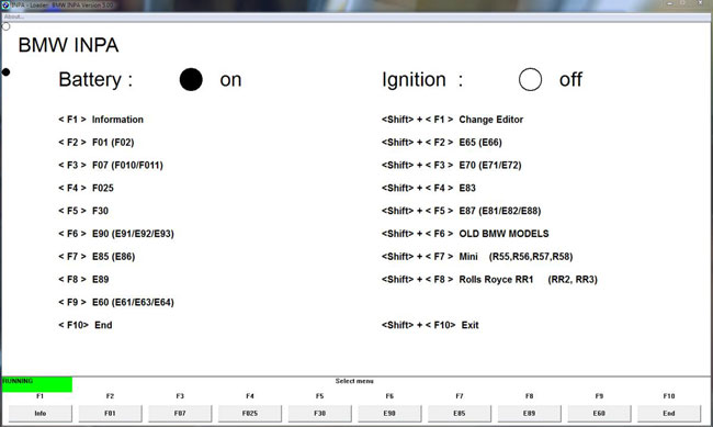
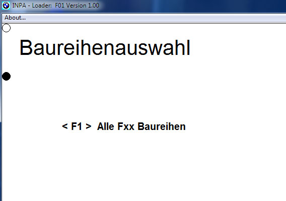
3. The Script selection window will appear. Select the 1st option on the right – FUNCTIONAL JOBS (Fig. 2).

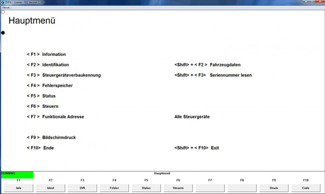

8. Select File->Load SGBD, Group file.
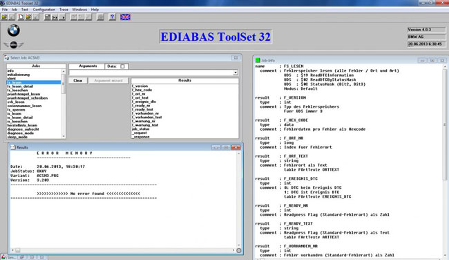
9. Browse to the EDIABAS\ECU folder, and search for the file name based on the listed yellow column entry. In this example, I’m loading the AIRBAG module file, named ACSM3.PRG (Fig. 6).

Posted by: jean at
07:25 AM
| No Comments
| Add Comment
Post contains 388 words, total size 6 kb.
February 06, 2017
Here is the knowledge about LCM and instruction on how to reset LCM module by using BMW ICOM A2 EDIABAS software.The Light Control Module (LCM) is an important component of a vehicle because it controls all of the car’s lights, as well as the horn function.
What functions are controlled by the LCM?
LCM controls all of the lights on the vehicle, including headlights, taillights, turn signals, brake lights, fog lights and hazard lights. Whether you are noticing issues with a specific light, or with sets of lights, such as high beams, low beams, or parking lights, My Auto Solutions can locate the issue within your LCM and provide a fix to get you safely back on the road.
How to Tell if your LCM is Broken?
There are many telltale signs of a malfunctioning LCM. If you notice any of the following problems, you may have a faulty Light Control Module in need of repair.
-Headlights do not turn on or are intermittent
-Certain or all taillights have stopped working
-Brake lights no longer function or are intermittent
-Turn signals do not blink or blink too quickly
-Emergency hazard lights do not blink or blink too quickly
-Dashboard does not illuminate
How to reset LCM module of BMW E60 2006? (customer share)
You needICOM A2 software EDIABAS tool32(it comes withINPA)
You need to find out which bulb has triggered the short circuit counter
Run the job "status_lampen_kurzschluss†and this will show whichbulbs are triggered with a 1, all other bulbs will show 0
Once you know the bulb, look up the bulb number in the Tabellen-info window, look for the LAMPNRTEXTE- it’ll look like this
0×00 AUSGANG_FL_LINKS Fernlicht links
0×01 AUSGANG_FL_RECHTS Fernlicht rechts
0×02 AUSGANG_AL_LINKS Abblendlicht links
0×03 AUSGANG_AL_RECHTS Abblendlicht rechts
0×04 AUSGANG_BEGRL_LINKS Begrenzungslicht links
0×05 AUSGANG_BEGRL_RECHTS Begrenzungslicht rechts
0×06 AUSGANG_NSW_LINKS Nebelscheinwerfer links
0×07 AUSGANG_NSW_RECHTS Nebelscheinwerfer rechts
0×08 AUSGANG_FRA_LINKS_VORN_1 Fahrtrichtungsanzeiger links vorne 1
0×09 AUSGANG_FRA_RECHTS_VORN_1 Fahrtrichtungsanzeiger rechts vorne 1
0x0A AUSGANG_FRA_LINKS_HINTEN Fahrtrichtungsanzeiger links hinten
0x0B AUSGANG_FRA_RECHTS_HINTEN Fahrtrichtungsanzeiger rechts hinten
0x0C AUSGANG_FRA_LINKS_VORN_2 Fahrtrichtungsanzeiger links vorne 2
0x0D AUSGANG_FRA_RECHTS_VORN_2 Fahrtrichtungsanzeiger rechts vorne 2
0x0E AUSGANG_BREMSLICHT_LINKS Bremslicht links
0x0F AUSGANG_BREMSLICHT_RECHTS Bremslicht rechts
0×10 AUSGANG_BREMSLICHT_MITTE Bremslicht mitte
0×11 AUSGANG_SL_BL_LINKS Schlusslicht/Bremslicht links
0×12 AUSGANG_SL_BL_RECHTS Schlusslicht/Bremslicht rechts
Run job "reset_kurzschluss_sperre†and in the Arguments box, type the lamp number you want to reset, for example 0×04 and run the job.
Finally, You can re-read the status again with status_lampen_kurzschluss and see if it has changed from 1 to 0.
http://obd2expresscouk.bcz.com/2017/02/06/reset-mw-e60-2006-lcm-module-via-ediabas/
Posted by: jean at
08:21 AM
| No Comments
| Add Comment
Post contains 415 words, total size 4 kb.
February 05, 2017

Posted by: jean at
07:14 AM
| No Comments
| Add Comment
Post contains 510 words, total size 11 kb.
February 04, 2017

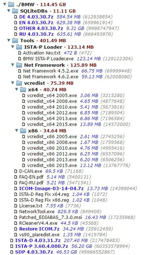
Instructions for installation, configuration and solution of possible errors, is located in theToolsfolder(FAQ-RU.pdfandFAQ-EN.pdf).
ISTA-P – 112 GB
Service Data (SDP) – 70 GB
Posted by: jean at
07:39 AM
| No Comments
| Add Comment
Post contains 126 words, total size 3 kb.
32 queries taking 0.1376 seconds, 205 records returned.
Powered by Minx 1.1.6c-pink.

